Roger “Skip” Ohman Jr. is a mechanical engineer with more than 30 years of experience in the rigging and lifting industry, including 18 years at The Crosby Group, where he was director of end-user training and director of international business development. Throughout his career, he has been involved with the Association of Crane & Rigging Professionals, National Commission for the Certification of Crane Operators, and a number of ASME B30 committees. Currently at Verde Concepts Inc., he provides technical and training development services for rigging hardware, chain, and the application of slings.
He notes there are two trends occurring in training: Using high-tech electronics and employing training models. “Electronics, which can be used to simulate, are wonderful, and there’s going to be more and more of it in the future,” he said. By comparison, models are more economical and allow the student to physically rig and lift a load.
Recently, Ohman partnered with Gregory Kane of TactiLearning LLC, an education company dedicated to the training and safety of rigging professionals. Their goal is to bring a hands-on experience to the rigging training process.
“People want more demonstrable skills that apply to the job rather than familiarization that you get from a presentation,” Ohman said. “Just doing classroom training with a PowerPoint and paper falls pretty far short of making sure that a person has the skill that translates into something they can do on the job.”
Using the model rigging training kit, Ohman has presented a Rigging Scenario. The scenario is explained, and one possible solution is presented, evaluated, and discussed.

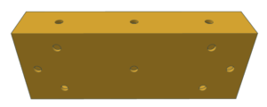
The load is a simple rectangular box with holes as locations for the attachment of eye bolts.
THE RIGGING OBJECTIVE
The Load
A simple rectangular box with holes as locations for the attachment of eye bolts.
The Rigging Equipment
- Two (2) slings
- Two (2) eye bolts
- Three (3) shackle
- One (1) masterlink
The Requirements

Create discussion points as outlined for this possible solution.
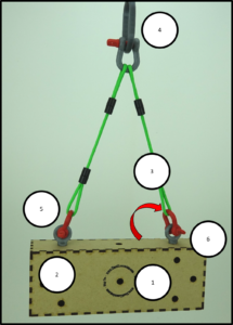
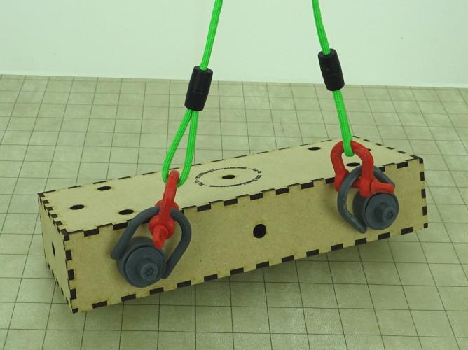
Using two slings, connect box load (on long edge) to master link with eye bolts. Create a horizontal sling angle of 60 degree (or greater) sling angle.
Discussion points for the rigging training instructor to determine the possible solution
- The Center of Gravity Location
- Pick Points Location
- Slings and Horizontal Sling Angle
- Connection of Slings to Master Link with Shackle
- Connection of the Slings to the Eye Bolts
- Application of Eye Bolts
Suggested Points for One Solution
- C.O.G. is located at center of box on both planes. The uniform box is constructed with uniform materials.
- Pick points for slings are at two outer holes on the top edge. This allows the connection of two slings equidistant from the C.O.G.
- The two slings selected provide for a horizontal sling angle greater than 60 degrees. This is determined by checking that the length of sling is greater than the distance across the pick points. It also can be determined by noting that the sling lenth is more than 1.15 times the height of the rigging triangle. The L/H for 60 degree horizontal sling angle is 1.15. The slings must be sized to carry its share of the load multiplied by L/H.
- The slings are connected to the master link with an appropriate-sized screw pin shackle. The screw pin shackle is used with recognition that the pin must be tightened with the pin placed in the master link. The shackle and master link must be sized to support the entire weight of the load and rigging.
- The slings are connected to the eye bolts with two appropriate-sized shackles. The shackle pin should be placed in the eye bolt and must be secure. The shackles must be sized for the same load as the slings.
- Eye bolts must be tightened against the load with the plane of the eye in line with the sling. The eye bolts must be de-rated for the angle of pull and the load on the eye bolt must be calculated the same as for the slings, including the sling multiplier (L/H < 1.15).

